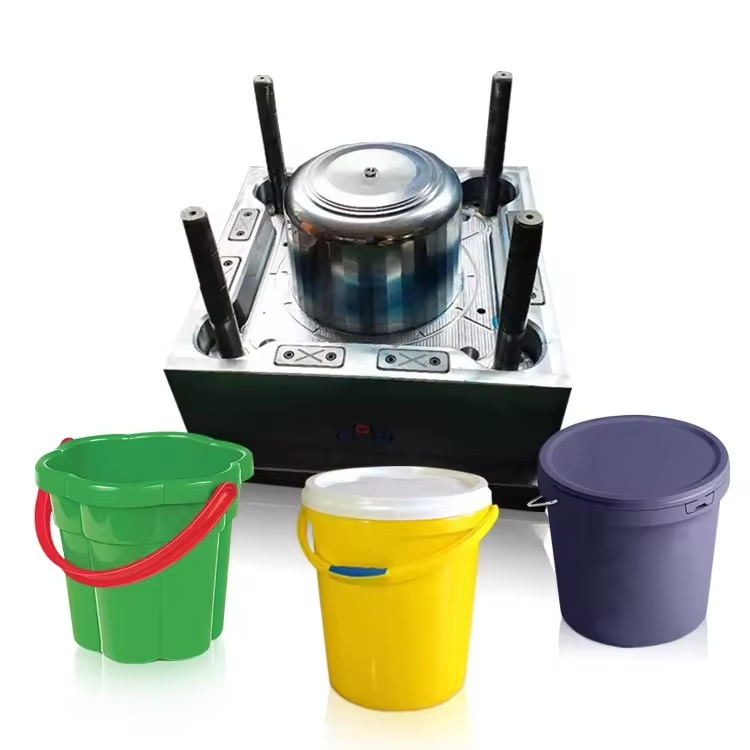
From first shots to production approval
A tool trial is a decision gate, not an automatic release.
A finished mold is a tool, not an approved production process. Before release, a buyer needs evidence that the intended resin can fill, cool and eject in that tool, and that parts made under recorded conditions meet the drawing and assembly requirements. The questions change as a program moves from first shots to measured samples and then to correction verification.
The checklist below helps sourcing, tooling and product teams agree on the result required from each trial. It is general engineering guidance, not a claim that every project needs three trials or that a T2 sample automatically authorizes mass production. The approved drawing and customer quality plan set the acceptance criteria.
By Nylon Plastic Technical Team
Reviewed by: Nylon Plastic Technical Team
What T0, T1 and T2 Mean
T0, T1 and T2 are common project labels, not globally enforced definitions. One supplier may call the first mold shot T0; another may call it T1. Agree in writing on each trial’s objective, sample count, inspection scope, report, decision owner and permitted next step before the tool is run. Manufacturer examples describe T0 as an initial tool-function check, T1 as an engineering-sample evaluation and T2 as a check of corrections and stability, but the exact project sequence can differ. [1, 2]
On a narrow screen, swipe this table sideways.
| Trial label in this guide | Decision to make | Minimum useful evidence | Possible disposition |
|---|---|---|---|
| T0 — initial tool and filling check | Can the tool operate and form a part that can be evaluated? | Tool-action observations, labeled parts, filling/defect photos, resin and process record, issue list | Correct tool/process; proceed to measured samples only when useful |
| T1 — engineering samples | Does the part approach drawing, appearance and assembly requirements? | Cavity-identified samples, measured critical features, defect map, fit/function findings, action owners | Approve corrections or expand validation |
| T2 — correction verification | Did each agreed correction work under repeatable, recorded conditions without new failures? | Before/after issue record, remeasurement, process record, samples from relevant cavities and run points | Continue corrections, request customer review or start required production validation |
T0 Trial: Check Tool Function and Basic Filling
At T0, confirm that the mold opens and closes, moving actions operate, parts release without damage, and the intended resin can form the geometry. Record incomplete filling or short shots, flash, burn marks, trapped air, gate vestige, sticking/ejection marks and obvious surface defects. Label the cavity and sampling conditions, and record what changed during the trial. Autodesk defines a short shot as incomplete cavity filling and notes that flow restriction, venting and temperature can contribute; a single defect is not proof that only the mold or only the settings are at fault. [1, 3]
The useful T0 output is a prioritized correction list: defect location, suspected cause, proposed mold or process action, owner and retest requirement. Unless the customer’s plan says otherwise, T0 samples are diagnostic, not final appearance or dimensional approval samples.
T1 Trial: Measure the First Engineering Samples
Run the documented material and a defined process, then inspect parts from every relevant cavity. Check the drawing’s critical dimensions using the agreed measurement method and conditioning time. Review appearance by defined cosmetic zones, plus weld lines, sink, warp, gate and ejector marks. Try the actual mating parts where available. If a snap fit, seal, insert, fastener or electrical clearance is critical, perform the applicable fit or functional check instead of inferring success from dimensions alone.
Compare measured results with the drawing revision and agreed acceptance criteria. Record the process conditions and identify samples by tool, cavity, date and trial. An acceptable part from one cavity or one short run does not establish all-cavity or production-rate repeatability. Decide whether each finding needs a drawing change, mold correction, material review, process adjustment or further testing. [1, 2, 4]
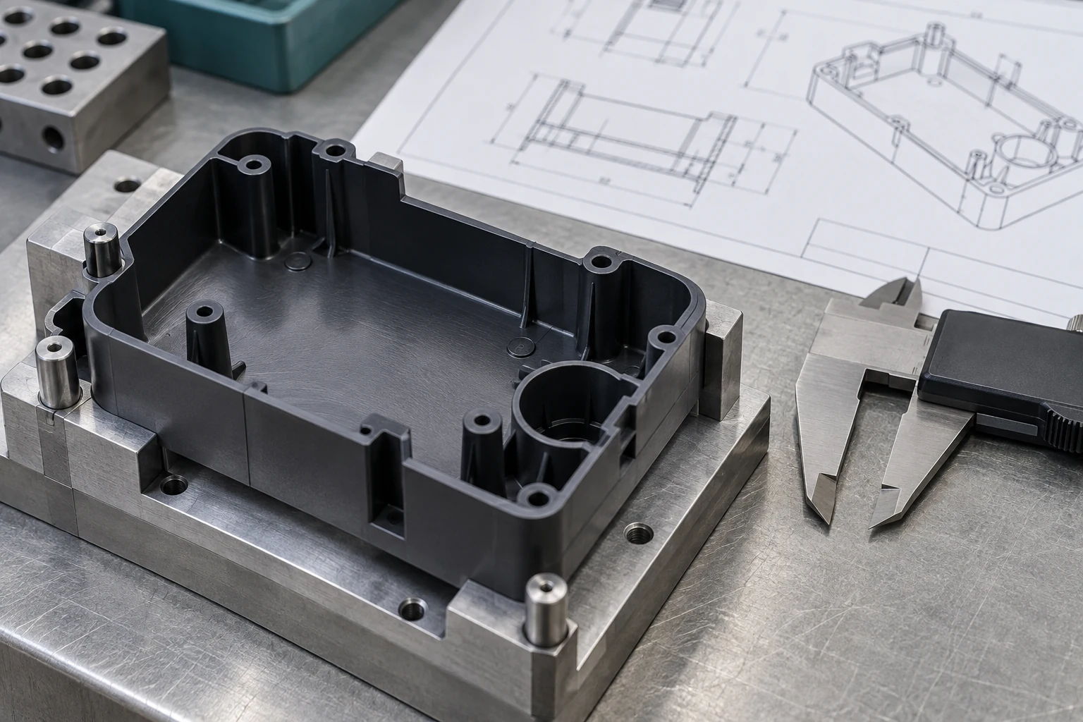
T2 Trial: Verify Corrections and Stability
Bring the T1 action list to the T2 trial. For each issue, connect the original evidence to the correction, the affected tool feature or setting, and the new measured result. Recheck other critical dimensions and cosmetic areas: moving a gate, changing cooling or increasing pack pressure can affect more than the defect being fixed. If several cavities exist, check the cavities affected by the correction as well as the rest of the tool as required by the inspection plan.
To assess stability, compare samples over an agreed run period and across the documented operating conditions needed for the intended production process. The customer and supplier should define the sample plan and acceptance limits; no generic T2 cycle count proves capability. If a requirement remains open, record a hold, corrective action and next trial instead of silently treating “T2 completed” as approval. [1, 2]
Mold Trial Conditions That Must Be Recorded
Record enough detail to repeat or investigate the result. At minimum, agree on:
On a narrow screen, swipe this table sideways.
| Catégorie | Trial record |
|---|---|
| Matériau | Manufacturer and exact resin grade, color/additive variant, lot number, recycled-content rule if relevant |
| Material condition | Drying equipment and settings, drying time, measured moisture where required, handling/conditioning before molding and inspection |
| Outil | Tool ID and revision, cavity ID, gate/hot-runner setup, changed inserts or steel corrections |
| Machine | Press ID, screw/barrel configuration if relevant, auxiliary equipment and actual production-intent setup |
| Thermal settings | Actual melt and mold temperatures, cooling settings and time |
| Fill and pack | Fill profile, injection pressure or pressure limit, transfer point, hold/pack pressure and time |
| Output | Cycle time, sample sequence and quantities, rejects and defect locations |
| Inspection | Drawing revision, measurement method, time after molding, conditioning state and cavity-by-cavity results |
Use the selected resin supplier’s current processing guidance for starting conditions. Nylon moisture state and, for glass-filled grades, fiber orientation can affect the result, so the specified condition must be recorded when comparing trial samples. BASF’s Ultramid guidance illustrates these effects for polyamide materials. Autodesk’s simulation guidance also identifies filling, air traps and shrinkage/warpage as related process and material outcomes. [3, 4, 7]
Mold Approval Checklist (Copy for Your Project)
Set a value or a clear “not applicable” decision in each row. An empty cell is not an approval.
On a narrow screen, swipe this table sideways.
| Check | Evidence or acceptance reference | Result / open issue | Owner / approval |
|---|---|---|---|
| Tool ID and revision | Tool drawing, correction record | ||
| Cavities represented | Cavity-labeled samples and inspection plan | ||
| Resin grade, color and lot | Approved material specification and lot record | ||
| Process record | Machine, drying and actual molding conditions | ||
| Dimensions | Approved drawing revision, critical-feature report | ||
| Aspect | Approved cosmetic standard and defect limits | ||
| Assemblage | Mating-part fit and agreed acceptance criteria | ||
| Functional tests | Drawing or customer test plan | ||
| Documents | TDS/COA/COC, FAI, PPAP or other named deliverables as applicable | ||
| Open issues | Action, owner, due date and retest requirement | ||
| Customer decision | Written approval, conditional approval or rejection |
See the site’s engineering tolerance guide for dimension-planning context and SPI surface finish guide for appearance terminology. The electrical connector molding guide shows how cavity, material and functional checks become more specific for one application. In the project itself, the approved drawing, surface specification and agreed inspection method control acceptance.
When FAI or PPAP Is Needed
Ask the customer which approval format applies. A first-article inspection documents a part against specified characteristics in the format required for the project. SAE AS9102C, for example, sets requirements for performing and documenting aerospace FAI; it complements customer and applicable statutory or regulatory requirements and does not automatically govern an unrelated plastic part. [5]
PPAP is an industry-standard production-part approval process used when required by a customer, especially in automotive supply chains. AIAG describes its purpose as showing that design and specification requirements can be met consistently in an actual production run at production rates. A few attractive trial samples, or a resin COA alone, cannot establish that. Agree on the submission level, production-intent conditions, cavity coverage, evidence package and customer sign-off. Do not assume that Nylon Plastic can supply a named PPAP package until the scope is confirmed for the project. [6, 8]
From Mold Approval to Production
A useful planning path is tool trials and corrections → agreed production-intent validation and any required FAI or PPAP evidence → customer disposition → release under the approved plan. This is a decision path, not a mandatory trial count or fixed pilot sequence. Place any pilot or run-at-rate activity according to the customer’s approval plan; a completed T2 trial alone does not release a mold for production. [6, 9]
Keep the approved resin, drawing, tool revision, cavity identifiers, inspection method and process record linked to the release decision. Define who must be notified if those inputs change. If a new resin grade is proposed after tool trials, return to sélection des matériaux and recheck the affected molding and part requirements rather than carrying approval forward by name alone.
Request a Mold / Part Review
Share the part drawing or model if available, the intended resin, expected quantity, critical dimensions, appearance requirements, assembly or functional tests, and the approval documents your customer requires. We can review the current trial stage, open issues and required inspection records, then confirm the tooling, sampling and quotation scope for your project. The available deliverables and approval plan must be agreed for the actual project.
For tooling scope, see mold design and mold making.
Technical References
This is general engineering guidance. Trial names, deliverables and approval authority must be set in the customer project plan.
- Joumon Enterprise, Mold Trial Stages — a mold manufacturer’s description of T0/T1/T2 trial use; one supplier practice, not a universal rule.
- Mastars, T0–T3 Injection Mold Trials — manufacturer explanation of terminology variation, sample evidence and change verification.
- Autodesk Moldflow, Troubleshooting Short Shots — definition and multiple possible causes of incomplete filling.
- Autodesk Fusion, Injection Molding Simulation Results — filling, air traps, shrinkage and warpage context.
- SAE International, AS9102C Aerospace Series – First Article Inspection Requirements — current aerospace-specific requirements for performing and documenting FAI.
- AIAG, Production Part Approval Process — PPAP purpose and production-rate context.
- BASF, Ultramid (PA) Product Brochure — moisture conditioning, glass-fiber orientation and warpage context for PA materials.
- AIAG, PPAP: Understanding and Reviewing Effectiveness — customer-specific requirements and submission levels.
- AIAG, PPAP 4th Edition Errata — the PPAP flowchart is illustrative, and some customers require a run-at-rate before warrant submission.