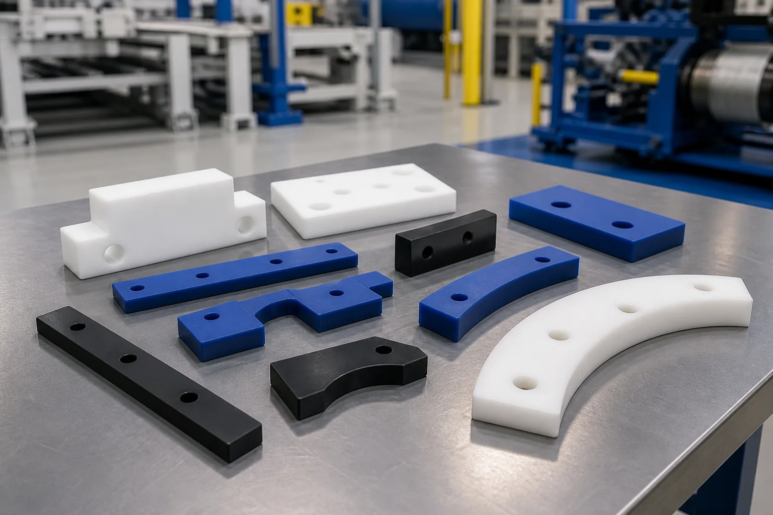
Plastic wear pads manufacturer selection should be based on contact pressure, motion, mating surface, operating temperature and the way the pad is supported. Custom wear pads protect frames, slides, carriages and heavy equipment by providing a replaceable polymer contact surface, but material choice alone does not correct poor alignment or insufficient bearing area.
For a useful quotation, send the assembly drawing or worn sample together with load, stroke or sliding speed, mounting method, required running clearance and target quantity. A supplier should review the pad as part of the load path rather than copy only its outside dimensions.
Replacement-part decision brief
Describe the Failure Before Choosing the Polymer
Uneven wear: check alignment, support and load direction.
Binding: check thermal or moisture growth and installed clearance.
Cracked holes: check wall section, fastener torque and corner geometry.
Short life: check debris, counterface roughness, pressure and speed.
Where Custom Plastic Wear Pads Are Used
Wear pads may support machine slides, telescoping sections, crane or lifting equipment, conveyor frames, material-handling carriages, dock or marine interfaces and replaceable guide blocks. Some move continuously; others carry a mostly static load and slide only during adjustment. These duty differences change the importance of friction, impact, creep and dimensional stability.
A pad installed on a rough, unsupported or misaligned frame will often wear at the edge regardless of resin quality. Before replacing the part, identify the true contact footprint and whether bolts, weld distortion or frame deflection prevent full support.
Select the Wear Pad Geometry Around the Assembly
| Wear Pad Form | Fonction type | Drawing Details to Control |
|---|---|---|
| Flat pad | Supports a slide, carriage, guide or replaceable wear face | Thickness, flatness, contact area and running clearance |
| Stepped or shouldered pad | Locates against a frame or protects an edge | Step datum, corner radius, assembly direction and load concentration |
| Curved pad | Supports pipe, drum, turntable or cylindrical motion | Mating radius, wrap angle, load direction and machining allowance |
| Counterbored pad | Keeps mounting hardware below the wear surface | Fastener head, residual wall, counterbore depth and replacement access |
| Bonded or backed pad | Combines a replaceable plastic face with a stiff support | Attachment method, differential expansion, edge sealing and service temperature |
Mounting holes should not be treated as simple clearance features. Countersinks and counterbores reduce the remaining wear section, and tight fasteners can distort a soft polymer. The design should keep hardware below the contact surface through the intended service interval and still leave enough material around each hole.
Material Direction by Load and Environment
| Orientation des matériaux | Point de départ commun | Design Caution |
|---|---|---|
| UHMW-PE | Low-friction sliding, impact and wet or dirty equipment | Lower stiffness and higher thermal movement can affect pad thickness, support and hole spacing |
| Cast nylon | Higher-load wear pads, slide blocks and replaceable bearing surfaces | Account for moisture absorption, temperature, creep and mating-surface condition |
| POM / acétal | Precision pads where dimensional stability and low moisture uptake matter | Check impact, edge loading, chemicals and temperature before substitution |
| Filled PTFE or bearing grade | Selected low-friction or chemical-service interfaces | Grade-specific creep, load capability and mating surface must be reviewed |
| PEEK or specialty polymer | High-temperature or aggressive chemical duty | Use only when the duty and required documentation justify the material cost |
Published material properties help screen candidates, but wear is a system result. Contact pressure, sliding velocity, counterface hardness and roughness, edge loading, contaminants and lubrication all affect service life. Regulated or food-contact applications require the exact grade and requested documentation; color or polymer family alone is not proof of compliance.
Define Installed Clearance and Replacement Limits
- Nominal clearance: identify the operating gap between the moving assembly and the wear surface.
- Minimum pad thickness: protect fastener heads, structural support and safe machine operation.
- Conditioning: state whether dimensions are controlled dry, conditioned or at operating temperature.
- Adjustment: document shims, slots or jacking features used to set the pad after installation.
- Inspection point: identify where maintenance personnel measure wear without dismantling the system.
- Replacement trigger: use a measurable thickness, clearance or movement limit instead of a visual guess.
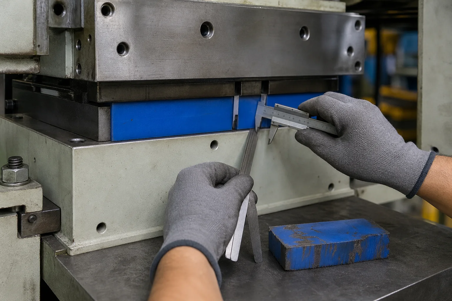
Thickness tolerance is important, but a close number on the drawing does not guarantee flat installed contact. Pad flatness, support surface condition, bolt pattern and tightening sequence may matter more. For curved pads, the mating radius and actual wrap determine whether load is distributed or concentrated at one edge.
Common Wear Pad Failures and Practical Fixes
| Observed Problem | Cause probable | Mesures correctives |
|---|---|---|
| Pad wears on one edge | The load is misaligned or the support surface is not flat | Correct alignment and support before increasing material hardness |
| Fastener head contacts the moving part | Counterbore depth or wear allowance is insufficient | Define minimum remaining wear thickness and inspection limit |
| Pad cracks around holes | Edge distance, countersink angle, press stress or bolt torque is too high | Increase section, use radii and control fastener loading |
| Machine binds after warm-up | Thermal growth or moisture expansion consumed running clearance | Set clearance from installed temperature and material conditioning |
| Pad creeps or takes a set | Contact pressure, temperature or unsupported span is too high | Increase bearing area, support the pad or choose a more suitable grade |
| Replacement part repeats short life | Only the worn shape was copied and the failure cause was ignored | Review load path, debris, lubrication, alignment and mating finish with the sample |
CNC Machining, Molding or Replaceable Liner?
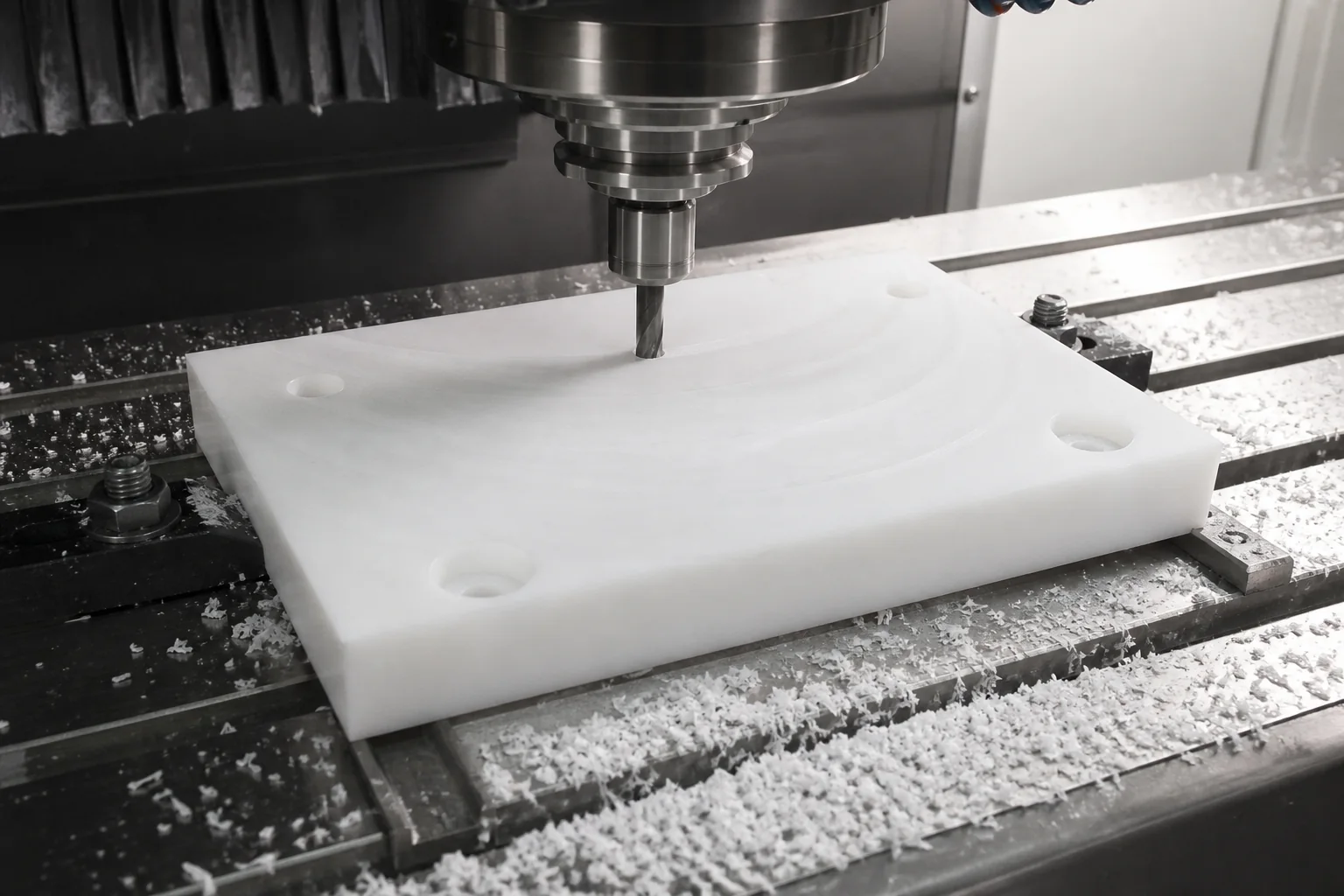
CNC machining is practical for custom profiles, repair parts, uncertain dimensions and low-to-medium volumes. It also allows pads to be made from plate, rod or tube with controlled counterbores, slots and curved surfaces. For larger quantities, nesting and common blank sizes can reduce material waste without changing the functional geometry.
Injection molding may suit a stable high-volume pad, but tooling, shrinkage, gate position, inserts and validation must be included in the business case. A thin replaceable liner on a rigid metal backing can sometimes control deflection better than a thick unsupported polymer block. The attachment and differential expansion still need engineering review.
Ressources techniques connexes
- UHMW CNC Machining Services for Wear Parts
- Nylatron Machining Services
- Matériaux des paliers en plastique et classes d'usure
- Pièces en plastique usinées sur mesure
Questions fréquemment posées
Que dois-je envoyer à un fabricant de patins en plastique ?
Veuillez nous envoyer un schéma ou un échantillon usé, les caractéristiques de la pièce d'accouplement, les charges, les mouvements, la température, les conditions environnementales, le mode de montage, le jeu requis, la quantité et le mode de défaillance actuel.
Quel matériau est le plus adapté pour une cale d'usure : l'UHMW ou le nylon ?
L'UHMW est souvent adapté aux applications nécessitant un faible coefficient de frottement, une résistance aux chocs et une utilisation en milieu humide, tandis que le nylon peut convenir à des charges plus élevées et à une plus grande rigidité. La géométrie, la pression de contact, la vitesse, l'humidité et la température déterminent le matériau le plus adapté.
How much wear allowance should a plastic pad have?
Wear allowance depends on pad thickness, fastener depth, required machine clearance and replacement interval. The drawing should identify a minimum safe remaining thickness rather than use a universal value.
Can you reverse engineer a worn plastic wear pad?
A sample can help identify profile and mounting, but wear may hide the original dimensions. The mating assembly and functional clearances should be measured before releasing the replacement drawing.
Should plastic wear pads be machined or molded?
CNC machining is usually suitable for replacement parts, custom geometry and low-to-medium quantities. Molding may reduce unit cost for stable high volumes after shrinkage, tooling and validation are justified.
Request a Custom Wear Pad Review
For a replacement slide pad, guide block or supported wear face, send the pad and assembly drawings or sample photos, including the current failure mode. Nylon Plastic has supported material selection and custom manufacturing since 2005; the review connects the pad, backing, fasteners, mating surface and required running clearance.
Éléments à inclure dans votre demande
- Files: released 2D drawing, 3D model, assembly view and revision; include a worn sample if available.
- Duty: normal and peak load, contact area, stroke, sliding speed, cycles and impact.
- Mating system: counterface material, hardness, finish, lubrication, debris and alignment condition.
- Environnement : temperature, humidity, immersion, cleaners, oils, chemicals, UV and outdoor exposure.
- Mounting: fastener size, torque, counterbore, backing plate, adhesive or captured installation.
- Acceptance: critical thickness, flatness, hole position, edge finish, inspection condition and report needs.
- Quantité et calendrier : prototype quantity, batch size, annual demand, target life and planned shutdown date.
- Material and release: exact grade or permitted alternative, minimum remaining wear thickness, conditioning, installed clearance and sample-approval method. Include destination, traceability and packaging needs; for material-only selection, identify the current grade and duty.
Compare quotes for the same material grade, stock, counterbores, backing or attachment scope, inspection condition and packaging. Confirm whether shims, backing plates, hardware, adhesive or assembled units are included. Agree replacement limits and the application check separately from dimensional inspection; a flat pad measurement alone does not approve load distribution in the installed assembly.