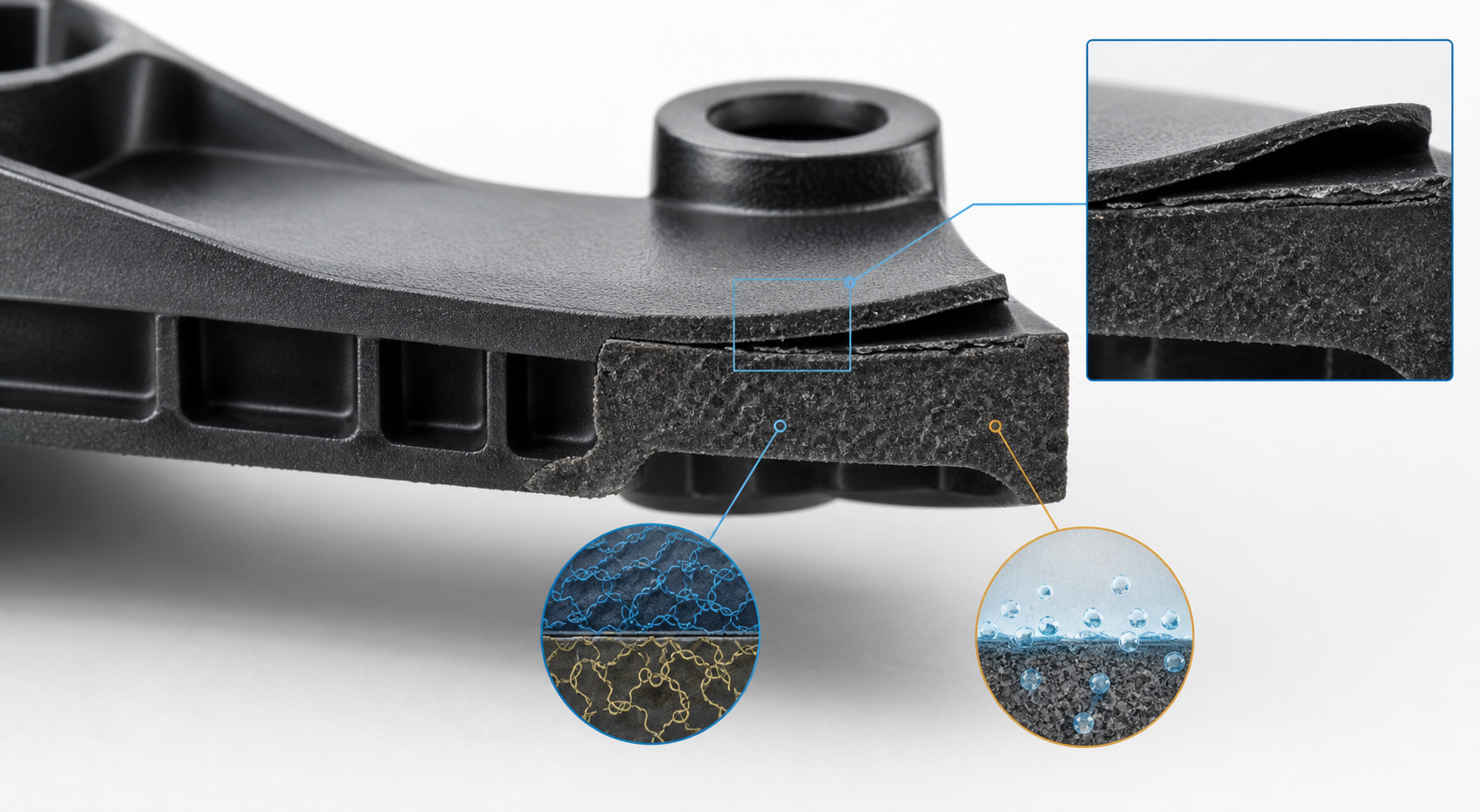
Delamination in injection molding is the separation of layers at or near the surface of a molded plastic part. It may look like peeling, flaking, a thin lifted skin, a white line, or a crack that opens when the surface is scratched or flexed. The mechanism is usually a weak interface caused by incompatible material, contamination, moisture, poor fusion, excessive shear, an unprepared insert or an overmold surface that was not ready to bond.
Delamination should be treated as a material and interface problem before it is treated as a simple temperature problem. Raising the melt temperature may improve fusion in one case but accelerate degradation or make contamination spread in another. A supplier needs the resin history, interface design, processing record and a sectioned sample to identify the failure mechanism with confidence.
What delamination looks like and why it matters
Surface delamination can appear at a flow line, gate area, weld-line region, sharp corner, insert interface or exposed edge. A thin layer may lift during trimming, ultrasonic welding, printing, painting or assembly. In a structural part, the separated layer can reduce impact resistance, fatigue life, sealing reliability or bond strength. In a cosmetic part, it can create a visible white or cloudy patch that grows after handling.
Not every surface line is delamination. A weld line, splay, paint failure, sink, knit mark or machining scratch can look similar in a photograph. Inspect the cross-section, examine the fracture surface and compare the defect with flow direction and material boundaries. If the feature occurs only after an overmolding step, the preparation of the first substrate may be more important than the second-shot settings.
Separate delamination from similar failures
| Observed feature | Possible mechanism | Useful confirmation |
|---|---|---|
| Thin skin peels from the molded surface | Weak fusion, contamination or incompatible material | Peel or cross-section inspection and resin identification |
| Silver or cloudy streak follows flow | Moisture, gas or surface splay | Drying record, moisture test and controlled dry-material trial |
| Line remains bonded but changes gloss | Weld line, orientation or texture transition | Short shot and flow-front comparison |
| Coating or ink lifts from plastic | Surface energy, cleaning or coating adhesion problem | Cross-hatch or adhesion test on the coating system |
| Overmold separates at the interface | Contamination, wrong substrate temperature or poor surface preparation | Interface section, peel test and substrate traceability |
| Layer separates after heating | Thermal expansion mismatch or weak interface | Thermal cycle with before-and-after inspection |
Le common injection molding defects guide is the broad reference for defect categories. The overmolding guide covers multi-material interface planning, while the injection molding service page covers the production route. This page focuses on identifying and correcting layer separation in molded and overmolded plastic parts.
Delamination cause, evidence and corrective action
| Cause group | Evidence to collect | Correction direction |
|---|---|---|
| Material compatibility | Resin family, grade, additive package, color and supplier lot | Verify material identity and use a qualified compatible pair |
| Contamination | Previous material, lubricant, release agent, oil, dust and regrind | Segregate material, clean equipment and control handling surfaces |
| Humidité | Drying temperature, time, dew point, moisture result and storage | Dry and store correctly, then confirm the material condition before molding |
| Process fusion | Melt temperature, mold temperature, fill speed, shear and residence time | Improve fusion within the grade window without promoting degradation |
| Interface preparation | Insert temperature, cleaning, plasma or primer, surface energy and delay time | Standardize preparation and protect the substrate before overmolding |
| Geometry and flow | Gate, weld line, thin wall, insert edge and local pressure | Review flow-front joining, gate shear, venting and interface support |
Material identification is important because a visually similar pellet can have a different carrier, additive package or processing temperature. A small amount of incompatible polymer can form a weak layer even when the bulk part looks correct. Regrind can carry colorant, moisture or degraded material from a previous run. The investigation should record material and equipment changes before process settings are changed.
Diagnostic sequence for a delamination complaint
- Preserve samples. Keep defective and acceptable parts from the same lot, cavity and production time. Do not scrape away the lifted layer before examination.
- Map the defect. Record whether it follows flow, a weld line, a gate, an insert edge, a rib or a cosmetic surface.
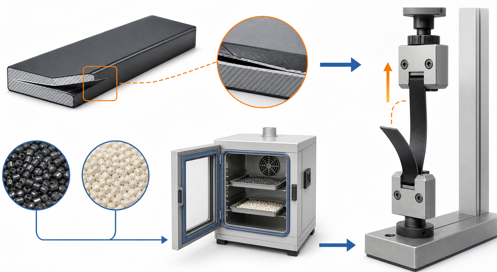
- Section the part. Use a controlled cut or polished cross-section to see whether the separation is at the surface, between polymers or inside a degraded layer.
- Inspect the fracture. Compare peel, burn and fracture appearance, and retain photographs at known magnification.
- Verify material and moisture. Check resin grade, lot, drying record, storage, moisture result and regrind content.
- Audit contamination. Inspect hopper, loader, barrel, screw, nozzle, hot runner, mold surface, inserts and handling gloves or release agents.
- Review interface and process. For overmolding, check substrate temperature, cleaning, delay, surface energy, clamp support and first-shot condition.
A simple peel test can screen interface strength, but it is not automatically a product acceptance test. Define the test direction, sample geometry, speed and failure mode. When the part is structural, use an application-representative tensile, shear, impact, pressure or fatigue test. The key result is whether the fracture occurs in the polymer, at the interface, or in a contaminated boundary layer.
Process corrections
Drying should be checked against the exact grade and part thickness, not only against a generic resin family. Moisture can create gas, hydrolysis or a weak interface. Storage after drying matters because open bins can reabsorb moisture before molding. Record dryer dew point, temperature, residence time and hopper transfer so the material condition is reproducible.
Melt and mold temperatures affect fusion, but higher is not always better. Increase fusion only inside the material supplier’s processing window and observe residence time, color change, gas and mechanical retention. Fill speed and back pressure influence shear and orientation. A stable, repeatable process is more valuable than one high-temperature trial that produces a clean appearance but degraded properties.
- Use verified material and segregate incompatible resins and color systems.
- Control moisture from drying through hopper delivery and molding.
- Minimize dead time and purge after material or color changes.
- Review melt, mold and insert temperatures together with residence time.
- Check venting and flow-front joining where the layer separates at a weld line.
- Keep the substrate clean and protected between preparation and overmolding.
Mold, DFM and overmold interface corrections
Geometry can create a weak layer when the flow front stretches over a sharp transition, traps gas against an insert or reaches an interface with insufficient pressure and heat. Gate position should support a controlled flow front across the bond area. Vents should release gas without allowing unacceptable flash. Insert edges should have enough support and radius to avoid a thin, poorly fused skin.
For overmolding, the first substrate needs a defined surface condition. Cleaning, drying, plasma, primer, texturing or mechanical preparation may be required depending on the material pair. The time between preparation and molding should be controlled because dust, moisture and handling can change the interface. The drawing should identify the bonded zone, allowable voids, peel direction and any required functional test.
When using a two-material process, do not approve a substitute substrate or elastomer only because it has a similar hardness. Compatibility, melt temperature, shrinkage, surface energy and chemical resistance must be considered together. A small pilot lot with sectioned samples is often more informative than a large production run that has not established interface evidence.
Validation and acceptance plan
Acceptance should combine visual, dimensional and functional evidence. Define the maximum visible area, acceptable edge lifting, peel force, leak rate, pull-off strength, impact result or retained property as appropriate. Use sectioned samples when the interface is hidden. Inspect both the beginning and end of the run because contamination and material residence can change during production.
For repeat orders, retain the resin and additive lots, drying record, substrate preparation record, process window, cavity and machine, first-article photographs and approved test results. If the defect appears after cleaning, color change, tool maintenance or a material substitution, the control plan should require a restart approval rather than relying on visual inspection alone.
Delamination prevention and RFQ checklist
- Provide CAD and drawing with the bonded, cosmetic and functional zones marked.
- Identify every resin, additive, color, insert, primer, adhesive and substitute.
- State moisture limits, drying conditions, storage time and regrind rules.
- Describe substrate preparation, handling, delay time and overmold sequence.
- Ask for compatibility, interface, gate, vent and flow-risk comments during DFM.
- Define sectioning, peel, adhesion, leak, impact or mechanical tests before tooling.
- Require material-lot and cavity traceability for defect samples.
- Approve a pilot lot and boundary samples before releasing repeat production.
For an RFQ or corrective-action request, send part photos, defective and good samples, resin and grade, interface material, cavity number, process sheet, drawing, annual volume and the function affected by separation. That evidence helps a supplier determine whether the first action is material segregation, drying, cleaning, process adjustment or mold/interface redesign.
Questions fréquemment posées
What is the fastest way to confirm delamination?
Preserve good and defective samples, inspect the surface without scraping it, then use a controlled cross-section and peel or fracture review. The failure location shows whether the weakness is at a material interface, surface layer or internal region.
Can delamination be fixed by process settings alone?
Sometimes moisture, fusion or residence-time control resolves the issue. If incompatible contamination, poor substrate preparation, a weak overmold pair or a trapped interface is involved, material and interface controls are required.
When does delamination require a mold modification?
Consider mold or DFM work when the separation follows a gate, insert edge, weld line or trapped-air location and remains after material, cleaning, drying and process controls are stable.
How should delamination be measured or accepted?
Use visual limits for cosmetic zones and application-specific peel, pull, leak, impact or mechanical criteria for functional zones. State the sample geometry, test direction, conditioning and failure mode.
What files should a supplier receive before troubleshooting?
Provide CAD, drawing, photos, defective and good samples, resin and grade, interface materials, preparation records, cavity and process data, annual volume and the required functional acceptance test.