
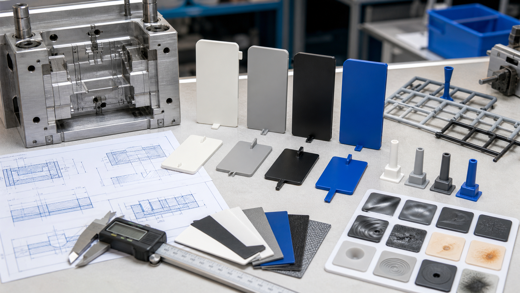
Injection mold parting line design determines where the mold separates, how the cavity is sealed, where vents and ejection can be placed, and where an unavoidable witness or mismatch will appear on the molded part. The best parting line supports robust mold construction, accessible finishing, reliable shutoffs and controlled flash while keeping the witness outside critical cosmetic, sealing and mating surfaces.
For a buyer, parting line approval should happen against the controlled CAD, drawing, cosmetic zones and assembly function. A line that is easy to machine may be unacceptable if it crosses a sealing edge or a visible housing face. A complex contoured split may improve appearance but add inserts, slides, wear and maintenance. The correct decision balances mold strength, ejection, venting, gate, cost, tool life and inspection limits.
The engineering function of a parting line
| Parting-line objective | What it controls | Evidence to review | Risk when overlooked |
|---|---|---|---|
| Reliable shutoff | Steel contact, cavity sealing and flash control | Shutoff geometry, support, angle, blue check and trial witness | Flash, wear, mismatch or repeated mold repair |
| Cosmetic placement | Visibility of witness, mismatch and gate-related marks | Viewing distance, texture, assembly and boundary sample | Visible line across a customer-critical face |
| Draw and ejection | Opening direction, undercuts, slides and ejector access | Motion review, draft map, retention side and ejection layout | Sticking, side action, distortion or an impossible opening sequence |
| Évacuation | Gas escape at the end of fill and around shutoffs | Flow-end map, vent path and maintenance access | Burns, short shots, weak weld lines or inconsistent fill |
| Tool strength | Steel support, insert edge and resistance to clamp/pressure load | Section thickness, support land, material and wear plan | Chipping, deformation, flash growth or premature tool failure |
Use the flash guide when an existing line has a leak or mismatch. The draft angle guide explains how draw direction and release geometry constrain the split. The Guide de conception des portails is useful when parting line, gate vestige and flow direction must be reviewed together.
Inputs that control the split
Start with the required draw direction and the surfaces that cannot move. Mark cosmetic faces, sealing edges, lens or texture areas, mounting planes, gasket grooves, snap features and interfaces that must remain free of mismatch. Then identify undercuts, side holes, deep ribs, inserts and moving features that may require a slide, lifter or separate insert.
Resin viscosity and shrinkage influence flash sensitivity and the amount of pressure reaching the split. Low-viscosity resins can find small clearances more easily. Glass-filled grades can increase wear at shutoffs and parting surfaces. Semi-crystalline materials can shrink onto cores and change the release load. The parting design should be checked against the expected pressure, tool steel, production volume, mold temperature and maintenance interval.
- Draw direction, undercuts, slides, lifters, inserts and ejection side.
- Cosmetic zones, texture, sealing surfaces, datums and assembly interfaces.
- Resin grade, viscosity, filler, shrinkage, mold temperature and flash sensitivity.
- Gate, runner, vent, end-of-fill, weld-line and air-trap locations.
- Tool steel, shutoff support, accessible finishing and expected tool life.
- Annual volume, automation, inspection method and allowed witness/flash.
Simple continuous split and robust shutoffs
A simple continuous split is usually easier to machine, finish, inspect and maintain. It should have enough steel behind the shutoff, a supported edge and a direction that does not force the mold to shear a thin steel lip. The shutoff angle must allow the mold to close and open without scraping or creating an unsupported knife edge. The parting line should be visible in sectioned CAD so the toolmaker and buyer can review actual steel conditions rather than only a colored surface boundary.
Contoured or stepped splits can keep a line out of a visible face or follow a complex housing, but they add transitions, inserts and opportunities for mismatch. A split that crosses a rib, boss or sealing feature should be checked for steel access, ejection and local packing. A parting line that is geometrically clean but impossible to vent or inspect is not a robust solution.
Material and production-volume effects
| Material or condition | Parting-line concern | Design response | Trial evidence |
|---|---|---|---|
| Low-viscosity resin | Small clearances can fill and create flash | Use supported shutoffs, controlled vent land and appropriate clamp/process window | Flash map, pressure trace and cavity comparison |
| Glass-filled resin | Abrasion can wear shutoffs and increase mismatch | Use suitable steel/hardening and define wear inspection | Long-run flash trend, blue check and shutoff measurement |
| Semi-crystalline resin | Shrinkage and thermal movement affect retention and mismatch | Review cooling, draft, core support and split relationship | Conditioned dimensions, release and parting-line witness |
| Textured cosmetic part | Witness and texture mismatch may be visible | Place split in a controlled zone or use a defined boundary sample | Light-angle inspection, texture and gloss comparison |
| High-volume production | Wear, debris and repeated clamp cycles change the split | Provide access, cleaning, blue-check and maintenance limits | Periodic witness, flash, alignment and wear record |
Tooling options and cost trade-offs
A simple two-plate split generally has the lowest construction and maintenance complexity when it can meet the part requirements. An insert can isolate a cosmetic or wear-sensitive area and make repair easier. A slide or lifter can form an undercut but adds motion, clearance, alignment and service requirements. A stepped split may improve cosmetics or steel support, but it should be reviewed for machining access and flash control at each transition.
| Option | Bénéfice | Trade-off | Suitable when |
|---|---|---|---|
| Simple continuous split | Low complexity and accessible finishing | May place witness across a visible or sealing surface | Part geometry supports a clean draw |
| Stepped/contoured split | Can move witness or follow complex geometry | More machining, transitions and mismatch points | Cosmetics or function justify added complexity |
| Replaceable insert | Local repair, texture and wear control | Fit, alignment, witness and insert cost | High-value or wear-sensitive feature |
| Slide/lifter split | Forms undercuts and side features | Motion, wear, clearance, cycle and maintenance | Undercut is essential to the part |
Failure modes and corrective actions
Flash can come from excessive cavity pressure, insufficient clamp, a worn or damaged shutoff, poor alignment, an incorrect vent condition or a parting line that lacks steel support. Mismatch may come from insert movement, guide wear, debris, thermal distortion or uneven support. A witness may be dimensionally harmless but visually unacceptable on a cosmetic face. Trapped air near a split can create burn marks or weak weld lines even when the parting line has no visible leak.
When a problem appears, map it by cavity and location. Inspect the split, blue check, guide system, vent, pressure trace, transfer, hold and mold-temperature condition. Avoid polishing a shutoff without knowing whether the problem is wear, alignment, pressure or venting. Removing steel can make a short-term flash repair permanent and reduce future adjustment options.
Validation at DFM, mold trial and approval
- DFM split review: mark draw direction, cosmetics, sealing, witness limits, undercuts and the proposed steel support.
- Motion and section review: check slides, lifters, inserts, ejection, vents, gates and finishing access.
- Blue check: verify contact and support before production-intent shots.
- Trial witness: inspect flash, mismatch, texture, drag, burn and end-of-fill evidence by cavity.
- Dimensional/cosmetic approval: measure critical interfaces and compare the accepted boundary sample.
- Maintenance approval: record cleaning, wear limits, blue-check frequency and repair decision rules.
DFM checklist and RFQ data package
- Provide CAD, drawing, resin, grade, texture, annual volume and tool-life target.
- Mark cosmetic, sealing, datum, assembly and prohibited-witness zones.
- State draw direction, allowed flash/mismatch, shutoff angle and datum relationship.
- Request sectioned parting-line review with steel support, vent, gate and ejection.
- Ask how blue check, trial witness, dimensional and cosmetic acceptance will be recorded.
- Define mold destination, automation, maintenance access and repair limits.
For an RFQ, identify where a parting line may be visible and where it cannot be accepted. We can then compare a simple split, insert, stepped split or side action against flash risk, tool life, cosmetics, cost and inspection evidence before tooling approval.
Questions fréquemment posées
How does parting line affect tooling cost?
A simple supported split is usually less expensive to build and maintain. Contoured splits, inserts, slides and lifters add machining, motion, alignment and inspection work, but may be justified to protect cosmetics, form undercuts or improve tool life.
Which drawing notes are needed for a parting line?
Mark cosmetic and sealing zones, allowed witness and flash, critical datums, draw direction, texture, assembly interfaces and any prohibited line location. State how mismatch and flash will be inspected.
How do glass-filled resins change parting-line design?
They can increase abrasion and directional shrinkage. Review steel hardness, shutoff support, alignment, cooling, draft and long-run wear evidence rather than approving the split only from a first-shot sample.
When should the mold concept change instead of adjusting process settings?
Change the concept when flash persists inside a stable process window, the split crosses a critical surface, the shutoff lacks steel support, or the vent/ejection arrangement cannot be maintained. Consider an insert, moved split, stepped split or side action.
How is a parting line validated during mold trials?
Use sectioned CAD, blue check, cavity-specific trial samples, flash and mismatch inspection, cosmetic boundary samples, critical dimensions and a documented maintenance/wear plan.